
Adjustment of a glue dispensing system
JULY-AUGUST 1998

Report written by : Jérôme BESSEYRIAS
Supervisors : Doctor Patrick SKUBIC and Mister Rusty BOYD
THANKS
First I would like to thank the Doctor P. L. Skubic to welcome me at the high-energy physics laboratory in the University of Oklahoma. Thanks to his dynamism and his hospitality I was given the opportunity to do an internship as gratifying humanly as technically. I would like to thank too the people who have helped me each day who have given me knowledge: Mr. G. R. Boyd and Mr. S. Krishnama.
INTRODUCTION
The laboratory of high-energy physics works on semiconductor detectors for use in high-energy physics experiment. This includes a flexible circuits which allow the link between the detector and the electronics. The work to do is to glue very small components (one millimeters long) on this flexible circuit. The right equipment to manipulate and glue such small components needed to be adjusted.
Table of contents
INTRODUCTION
I Presentation of the laboratory and of the topic of the internship click here => *
I.1 The laboratory of high energy physics click here => *
I.1.1 The Doctor Patrick L. Skubic
click here => *I.1.2 The Atlas experiment
click here => *I.1.3 The CLEO experiment
click here => *I.2 Presentation of the internship click here => *
II Presentation of the equipment click here => *
II.1 How to see the components? click here => *
II.2 How to manipulate the components? click here => *
II.3 How to glue the components? click here => *
II.3.1 The assembly station
click here => *II.3.2 The glue
click here => *III Results click here => *
III.1 Tests with the glue alone click here => *
III.1.1 The H20E
click here => *III.1.2 The EG105
click here => *III.1.3 The E2101
click here => *III.1.4 The 10HTS
click here => *III.1.5 The 10HTN
click here => *III.1.6 Summary
click here => *III.2 Tests of gluing a component click here => *
III.2.1 First set click here => *
III.2.2 Second set
click here => *III.2.3 Third set
click here => *III.2.4 Fourth set
click here => *III.2.5 Fifth set
click here => *III.2.6 Sixth set
click here => *III.2.7 Seventh set
click here => *III.2.8 Eighth set
click here => *III.2.9 Ninth set
click here => *III.2.10 Summary
* click here =>III.3 Conclusion and choice click here => *
CONCLUSION
ANNEX
I Presentation of the laboratory and of the topic of the internship
I.1 The laboratory of high energy physics
The OUHEP is managed by Dr P. Skubic. This laboratory works on the preparation of two experiments: "ATLAS" and "CLEO".
I.1.1 The Doctor Patrick L. Skubic

The area of research of Dr P. Skubic is experimental elementary particle physics. His present interest in this field is in experiments that produce particles containing the newly discovered "bottom" or "beauty" quark ("bottom-flavored" particles). He also has a strong interest in the development of semiconductor detectors for use in high-energy physics experiment and he is currently involved in several major efforts in the continued development of these detectors.
I.1.2 The Atlas experiment
For twenty years, experiments and observations helped to confirm the prediction of The Standard Model and especially to observe a certain number of quarks (the quark TOP was discovered in April 1995 at Fermilab). In order to further demonstrate this theory, experiment at very high energy level (about one TeV) must be performed. Only at these energy levels new particles such as the Higgs boson may be observed.
The Higgs boson:
The Standard Model has a proposal to explain this question: « Why do the fundamental particles have mass, and why are their masses different? ». Most of scientists are familiar with electric, magnetic and gravitational fields. The Standard Model proposes that there is another field, never before observed, a field that is almost indistinguishable from empty space. The Standard Model calls this the Higgs field. The Standard Model says that all of space is filled with this field, and that by interacting with this field, particles acquire their masses. Particles that interact strongly with the Higgs field are heavy, while those that interact weakly are light. The Higgs field has at least one new particle associated with it: the Higgs boson.
A very efficient detector is needed to see such particle. The ATLAS detector will be able to detect this particle if it exits.
This detector is due to begin in the year 2005 at the LHC (Large Hadron Collider) at the CERN. A picture of the LHC is showed in annex, page I. The diagram 1 shows the position of the ATLAS detector at LHC.
The ATLAS detector consists of four major components:
¯ The inner tracker: measures the momentum of each charged particle.
¯ The calorimeter: measures the energies carried by the particles.
¯ The muon spectrometer: identifies and measures muons.
¯ The magnet system: create a strong magnetic field over a huge volume.
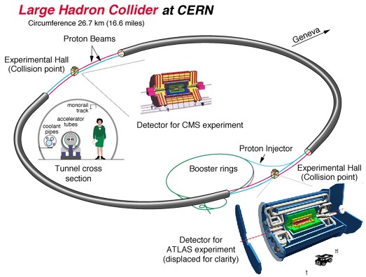
Diagram 1 : Position of the detector at LHC
To have more information about Atlas you can check this web site: http://atlasinfo.cern.ch/Atlas/public/Welcome.html .
I.1.3 The CLEO experiment
CLEO is a multipurpose high energy physics detector incorporating excellent charged and neutral particle detection and measurement, used to analyze electron-positron collision events generated by the CESR (Cornell Electron positron Storage Ring). The CLEO detector is operated by a collaboration of over 100 physicists from many institutions. A picture of the CLEO detector is showed in annex, page II.
The CESR is an electron-positron collider with a circumference of 768 meters, located on the Cornell University campus. It is capable of producing collisions between electrons and their anti-particles, positrons, with center-of-mass energies between 9 and 12 GeV. When an electron and a positron collide and annihilate, there is a flash of energy that is studied with a large and complex detection apparatus called the CLEO detector. The diagram 2 shows the position of the CLEO detector at CESR.
Diagram 2 : the position of CLEO at CESR
To have more information about Cleo you can check this web site: http://www.lns.cornell.edu/public/lab-info/cleo.html .
I.2 Presentation of the internship
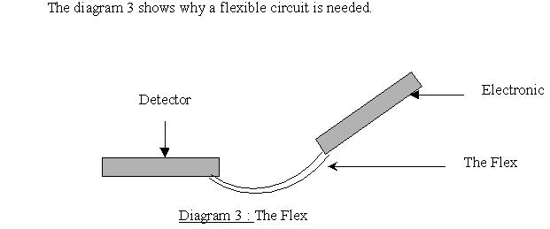
A key component of the CLEO experiment is the unit that links the detector with the electronics. These two parts are not located in the same plan. That’s why the circuit is a flexible circuit. This Flex was made by GECRD. (General Electric Corporate Research and Development).
The purpose of the internship is to set up a glue dispensing system able to glue small components on similar circuits to be used for ATLAS. The major problem comes from the size of the components and of the pads of the circuit. Indeed the resistors that are needed to be glued are 1 mm long, 0.5 mm large and 0.2 mm high.To glue such small components the laboratory had to buy and to test special equipment that is shown in the next paragraph.
II Presentation of the equipment
To glue components, the three major problems are:
¯ How to see the components?
¯ How to manipulate the components?
¯ How to glue the components?
II.1 How to see the components?
To see the components the laboratory has bought a microscope. It can magnify four times the component. It comes from Scienscope International Corp. .
II.2 How to manipulate the components?
It is almost impossible to manipulate such small components with tweezers. That’s why a vacuum pen is used. A very small tip is used with the vacuum pen: 0.2 mm of diameter. When the component is close to the pen, the pen sucks and holds it. It’s now easy to move the component with the pen. To move the component with precision the pen is held by a support. This support has a z axis micrometer screw. The Flex is on another support that has two another micrometric screws. It is the way to move the component in all the directions with a precision of 0.001 millimeter. A diagram of this assembly is shown in annex, page III.
II.3 How to glue the components?
To glue the resistor with precision < 1/2 millimeter the laboratory has bought a glue dispenser and special glues.
II.3.1 The assembly station
To glue such small component (one millimeter long) < half-millimeter glue dots are needed. To do this the laboratory has bought a dispensing system: the 1500XL from EFD Dispensing Components Stocking. With this glue dispenser it is possible to choose the time and the pressure of the compressed air into the syringe. The syringe has an interchangeable 0.16 mm diameter nozzle. With this small tip it is easy to do half-millimeter glue dot.
II.3.2 The glue
The laboratory has bought five different glues and many tests have been made to allow making a choice. The results of these tests are shown in the third paragraph. Here are presented the properties of the glues.
The H20E
This glue is made by EPOXY TECHNOLOGY INC. It is a two component silver epoxy. The first part is epoxy resin and silver powder. Th second is hardener and silver powder. The silver decreases the volume resistivity but increases the price: 100 dollars for 1 pound. To use the glue, the 2 parts have to be mixed in a 1/1 ratio (by weight or by volume). The pot life is 4 days at room temperature. A mix is needed before each use. After the application of the glue, a heat cure is needed.
Cure schedule :
Here are some properties given by EPOXY TECHNOLOGY, INC :
The EG105 :
This glue is made by EPOXY TECHNOLOGY, INC. It’s a single component glue. It contains silver powder too. The EG105 needs an UV precure and a heat cure.
UV precure: 100 mW/cm square for 1-2 min at 480 nm
Cure schedule:
The EG105 was cured at 120 degrees C during 60 minutes.
Here are some properties given by EPOXY TECHNOLOGY, INC :
The E2101 :
This glue is made by EPOXY TECHNOLOGY, INC. It is a two components silver epoxy. The first part is the silver powder and the second is the hardener. The silver decreases the volume resistivity but increases the price: 100 dollar for 1 pound. To use the glue, the 2 parts have to be mix in a 3/1 ratio (by weight). The pot life is 3 days at room temperature. A mix is needed before each use. After the application of the glue, a heat cure is needed.
Cure schedule:
The E2101 was cured at 175 degrees C during 15 minutes.
Here are some properties given by EPOXY TECHNOLOGY, INC :
The 10HTN :
This glue is made by MASTER BOND INC. It’s a single component, heat curing, high purity Nickel conductive epoxy. After the application of the glue, a heat cure is needed.
Cure schedule :
The minimum cure temperature is 110 degrees C. The 10HTN was cured at 120 degrees C during 1 hour.
Here are some properties given by MASTER BOND INC:
The 10HTS :
This glue is made by MASTER BOND INC. It’s a single component, heat curing, high purity Silver conductive epoxy. After the application of the glue, a heat cure is needed.
Cure schedule :
The minimum cure temperature is 110 degrees C. The 10HTS was cured at 120 degrees C during 1 hour.
Here are some properties given by MASTER BOND INC:
The first part of the work was to choose the most efficient glue. The laboratory has got five different glues: the H20E, the EG105, the E2101, the 10HTN and the 10HTS. Different tests have been made to allow making a good choice. After choosing the most efficient glue, the laboratory will have to begin the gluing of components on the Flex.
Two different tests were done to measure the electrical and mechanical resistance of the glues. The purpose of the first test that has been done with the glue alone is to measure the properties of the glue. The purpose of the second test that has been done with a component glued on a circuit is to show how is the comportment of the glue in real use.
III.1 Tests with the glue alone
The slides have been cured. The cure is different for each kind of glue. After the cure, two measures have been made: electrical resistance and mechanical resistance.
The H20E was cured at 120 degrees C for 15 minutes.
¯
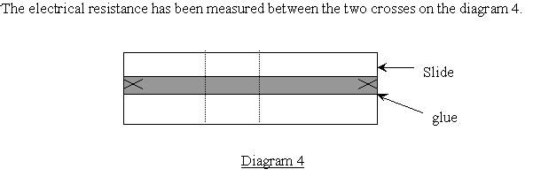
The electrical resistance
The result of the test is in table 1.
|
1 |
2 |
3 |
4 |
5 |
6 |
7 |
8 |
9 |
average |
|
|
H20E (ohm) |
40.5 |
31.6 |
32.9 |
4.9 |
12.1 |
1.8 |
2.9 |
4.6 |
1.9 |
14.8 |
Table 1
The three first slides have been made with a wood spatula. For the next slides an another slide has been used to put the epoxy. Perhaps the slides made with the wood spatula are less even than the other. This could be the reason of the high values.
¯
The mechanical resistance
There was no epoxy of the strip of scotch tape after the test. The mechanical resistance of H20E is good.
The EG105 was cured at 120 degrees C for 60 minutes. But the UV cure was missing (no lamp!).
¯
The electrical resistance
The result of the test is in table 2.
|
1 |
2 |
3 |
average |
|
|
EG105 (ohm) |
0.416 |
0.219 |
0.225 |
0.287 |
Table 2
¯
The mechanical resistance
There were approximately 20% of the strip covered by the EG105. Two other mechanical tests have been made and each time it was the same result: 40% of the strip covered by the EG105.
After each mechanical test, the electrical resistance has been measured:
After the first: 0.5 ohm
After the second: 15.6 ohms
After the third: 205 ohms
The E2101 was cured at 175 degrees C for 15 minutes.
¯
The electrical resistance
The result of the test is in table 3.
|
1 |
2 |
3 |
4 |
5 |
6 |
7 |
8 |
9 |
average |
|
|
E2101 (ohm) |
0.551 |
0.528 |
0.484 |
0.857 |
0.623 |
0.634 |
0.613 |
Table 3
¯
The mechanical resistance
There was no epoxy of the strip of scotch tape after the test. The mechanical resistance of E2101 is good.
The 10HTS was cured at 120 degrees C for 60 minutes.
¯
The electrical resistance
The result of the test is in table 4.
|
1 |
2 |
3 |
4 |
5 |
6 |
average |
|
|
10HTS (ohm) |
199 |
147 |
89 |
525 |
430 |
762 |
359 |
Table 4
¯
The mechanical resistance
There was no epoxy of the strip of scotch tape after the test. The mechanical resistance of 10HTS is good.
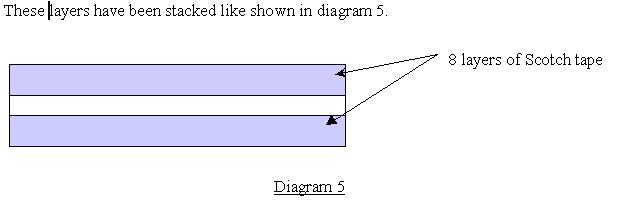
The 10HTN was cured at 120 degrees C for 60 minutes. The 10HTN is very thick. It doesn’t stick on the slide. That’s why eight layers of scotch tape have been used to make the slides.
¯
The electrical resistance
The result of the test is in table 5.
|
1 |
2 |
3 |
average |
|
|
10HTN (ohm) |
18.2 |
18.4 |
18.2 |
18.3 |
Table 5
¯
The mechanical resistance
There was no epoxy of the strip of scotch tape after the test. The mechanical resistance of 10HTN is good.
The results of the first test are summarized in the table 6.
|
FIRST TEST |
||||||||||||
|
1 |
2 |
3 |
4 |
5 |
6 |
7 |
8 |
9 |
average |
|||
|
H20E 2 components |
40.5 |
31.6 |
32.9 |
4.9 |
12.1 |
1.8 |
2.9 |
4.6 |
1.9 |
14.8 |
OK |
|
|
EG105 single |
.416 |
.219 |
.225 |
0.287 |
BAD ( no UV cure) |
|||||||
|
E2101 2 components |
.551 |
.528 |
.484 |
.857 |
.623 |
.634 |
0.613 |
OK |
||||
|
10HTS single |
199 |
147 |
89 |
525 |
430 |
762 |
359 |
OK |
||||
|
10HTN single |
34000 |
10000 |
6600 |
18.2 |
18.4 |
18.2 |
18.3 |
OK |
||||
Table 6
The mechanical test of EG105 is bad but there was not done an UV precure. The relationship between the UV precure and the mechanical resistance can not be demonstrated because the laboratory has not an UV lamp.
The three first measures of the electric resistance, for the 10HTN, have been made with one layer of scotch tape. 10HTN is very thick and does not stick to the slide. That’s why the measures are huge. The three next measures have been made with a height of eight layers of scotch tape.
III.2 Tests of gluing a component
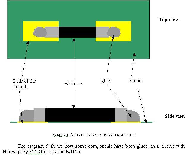
The circuit and the components have been cured. After the cure two tests have been made: an electrical test and a mechanical test. The first is to measure the electrical resistance of the components and the second is to measure the mechanical resistance with a force calibration meter.
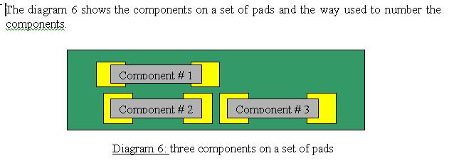
Nine sets of pads have been used to glue the components.
Two components (39 ohms) have been glued with EG105 (single component). The UV cure has not been made. The cure was 120 degrees C for 60 minutes.
The result of the test is in table 7.
|
Resistance (ohm) |
Strength test (kg) |
|||
|
1 |
2 |
3 |
||
|
1st set of pads (EG105) |
27.7 |
13 |
||
Table 7
Three components (39 ohms) have been glued with H20E (2 components). They have been cured at 120 degrees C for 15 minutes.
The result of the test is in table 8.
|
Resistance (ohm) |
Strength test (kg) |
|||
|
1 |
2 |
3 |
||
|
2nd set of pads (H20E) |
39.06 |
38.7 |
39.27 |
1.16 and 1.25 |
Table 8
Three components (39 ohms) have been glued with H20E. They have been cured at 120 degrees C for 15 minutes
The result of the test is in table 9.
|
Resistance (ohm) |
Strength test (kg) |
|||
|
1 |
2 |
3 |
||
|
3rd set of pads (H20E) |
19.56 |
39.2 |
||
Table 9
Three components (39 ohms) have been glued with H20E (2 components). They have been cured at 120 degrees C for 15 minutes.
The result of the test is in table 10.
|
Resistance (ohm) |
Strength test (kg) |
|||
|
1 |
2 |
3 |
||
|
4th set of pads (H20E) |
38.94 |
19.52 |
38.97 |
2 |
Table 10
Three components (39 ohms) have been glued with H20E (2 components). They have been cured at 120 degrees C for 15 minutes.
The result of the test is in table 11.
|
Resistance (ohm) |
Strength test (kg) |
|||
|
1 |
2 |
3 |
||
|
5th set of pads (H20E) |
39.2 |
13 |
19.6 |
|
Table 11
Three components (39 ohms) have been glued with 10HTN (single component with 10% of acetone by weight). They have been cured at 120 degrees C for 60 minutes.
The result of the test is in table 12.
|
Resistance (ohm) |
Strength test (kg) |
|||
|
1 |
2 |
3 |
||
|
6th set of pads (10HTN) |
55.25 |
69.1 |
49.36 |
|
Table 12
Three components (39 ohms) have been glued with 10HTN (single component with 10% of acetone by weight). They have been cured at 120 degrees C for 60 minutes.
The result of the test is in table 13.
|
Resistance (ohm) |
Strength test (kg) |
|||
|
1 |
2 |
3 |
||
|
7th set of pads (10HTN) |
62 |
63.2 |
54.3 |
|
Table 13
Three components (39 ohms) have been glued with E2101 (2 components). They have been cured at 175 degrees C for 15 minutes.
The result of the test is in table 14.
|
Resistance (ohm) |
Strength test (kg) |
|||
|
1 |
2 |
3 |
||
|
8th set of pads (E2101) |
40.24 |
39.33 |
39.31 |
|
Table 14
Three components (39 ohms) have been glued with E2101 (2 components). They have been cured at 175 degrees C for 15 minutes.
The result of the test is in table 15.
|
Resistance (ohm) |
Strength test (kg) |
|||
|
1 |
2 |
3 |
||
|
9th set of pads (E2101) |
40.89 |
39.97 |
41.52 |
1.1 |
Table 15
All the results of the second test are summarized in table 15
|
SECOND TEST |
||||
|
Resistance (ohm) |
Strength test (kg) |
|||
|
1 |
2 |
3 |
||
|
1st set of pads (EG105) |
27.7 |
13 |
||
|
2nd set of pads (H20E) |
39.06 |
38.7 |
39.27 |
1.16 and 1.25 |
|
3rd set of pads (H20E) |
19.56 |
39.2 |
||
|
4th set of pads (H20E) |
38.94 |
15.9 |
38.97 |
2 |
|
5th set of pads (H20E) |
39.2 |
13 |
19.6 |
|
|
6th set of pads (10HTN) |
55.25 |
69.1 |
49.36 |
|
|
7th set of pads (10HTN) |
62 |
63.2 |
54.3 |
|
|
8th set of pads (E2101) |
40.24 |
39.33 |
39.31 |
|
|
9th set of pads (E2101) |
40.89 |
39.97 |
41.52 |
1.1 |
Table 15
The conclusion and the choice of the glue have been made with the results of the first test. The purpose of the second test is to verify the comportment of the glue in real use.
There are two criterions for the choice of the glue: it must have a low electrical resistance and it must resist the mechanical test.
The study of the table 6 shows that there are four glues with a very low electrical resistance: the EG105, the H20E, the 10HTN and the E2101. The average of theirs resistance is 0.287 ohms (EG105), 14.8 ohms (H20E), 18.3 ohms (10HTN) and 0.613 ohms (E2101). The EG105 has not resisted the mechanical test and the 10HTN is not easy to use. That's why the choice should be the E2101 or the H20E. The second test shows that theirs comportment are good. The E2101 or the H20E should be the glue used to glue components on the Flex.
But more tests have to be done before a decision is made.
Conclusion
This internship has helped the high-energy physics laboratory to choose and to set up the right equipment used to glue small components on a flexible circuit.
Thanks to this internship I have learned a lot of knowledge in a new field for me: the micro-electronic. I have learned much humanly and technically. This internship gave to me the opportunity to work with people who have different language and different culture. That's why this stay in United States was very gratifying.
Annex

The Large Hadron Collider at the CERN
The CLEO detector
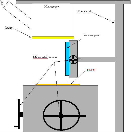
Diagram of the assembly